Newest progress reports are at the bottom of the page
I will try and update this page with new photos at least every 3-4 days. The date at the end of the caption is when the photo was uploaded. The actual progress of the layout is a little ahead of what you see here.
August 2010 - January 2011
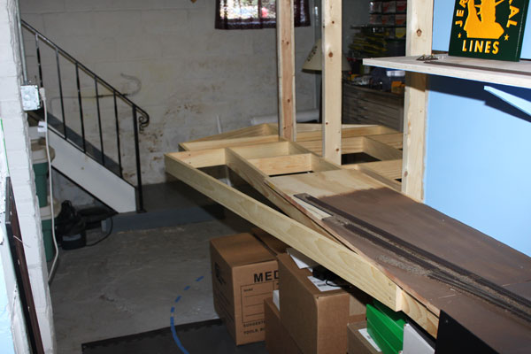
Construction begins on phase two of the layout which will bring the NY&LB through Point Pleasant Beach and to the Manasquan River bridge. (8/29/10)
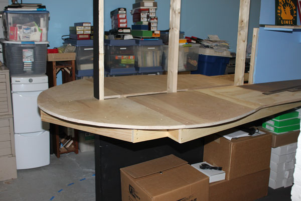
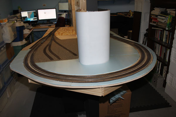
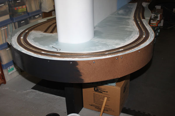
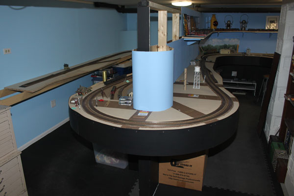
Here the line must make a 180 degree turn at the end of the peninsula. I had to settle on a 30 degree radius for the outer double track on this curve. (8/29/10)
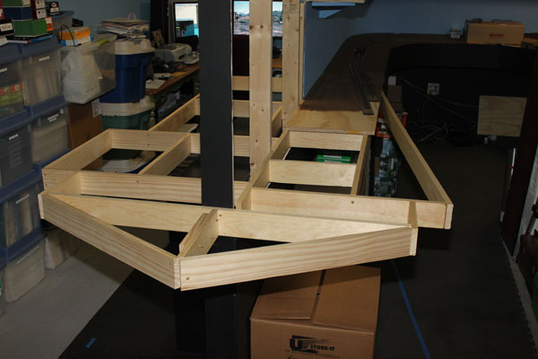
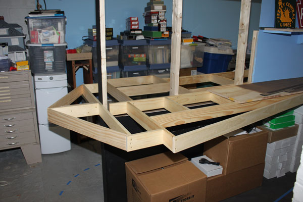
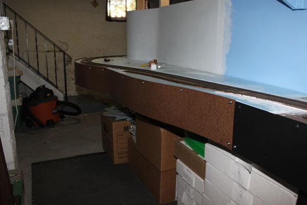
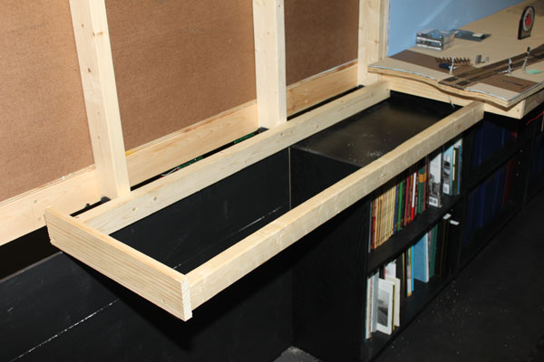
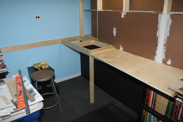
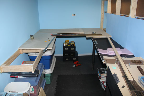
The bench work here was a bit complicated, but is very stable. The jury is still out on whether I will need to add support legs here in the future. (8/29/10)
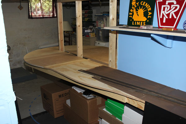
The Manasquan River will be where the calendar is. Over the above bench work is the future Point Pleasant Beach station and freight yard sidings. (8/29/10)
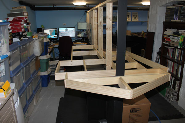
This photo gives a good indication of how rapidly the room is filling up with the layout. My temporary office is in the far corner. (8/29/10)
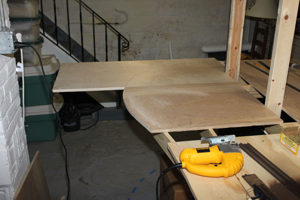
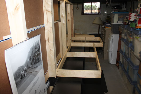
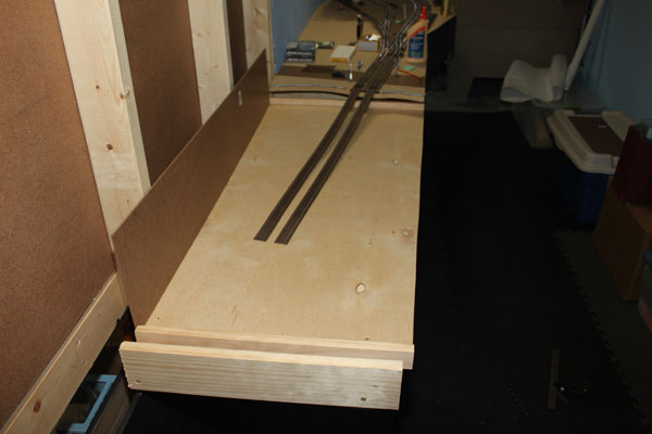
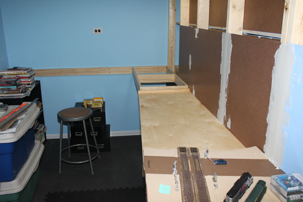
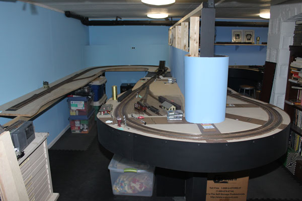
3/4 inch birch plywood top starts to take shape. I had to position the 180 turn so it didn't extend more than 16 inches from the end of the peninsula wall for aisle clearance. (8/29/10)
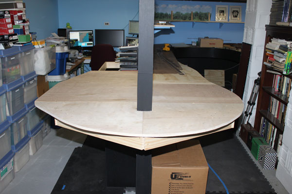
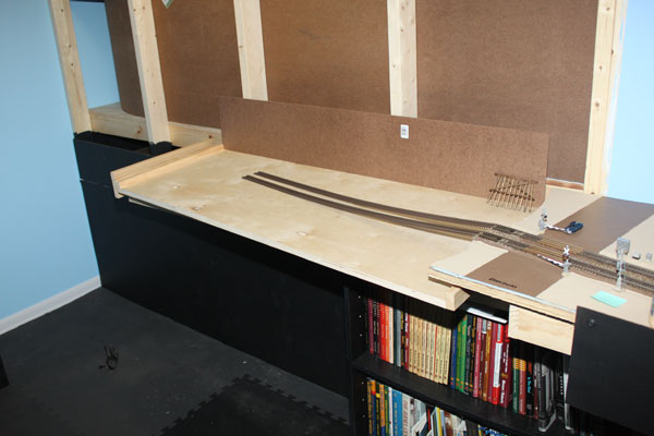
With most of the plywood down, I could get a better idea of what I was in for as far as aisle clearances and room for scenery. (8/29/10)
Point Pleasant Beach station is on the right edge of the layout here, while to the left is the freight station and several sidings for lumber deliveries and RPO cars. (8/29/10)
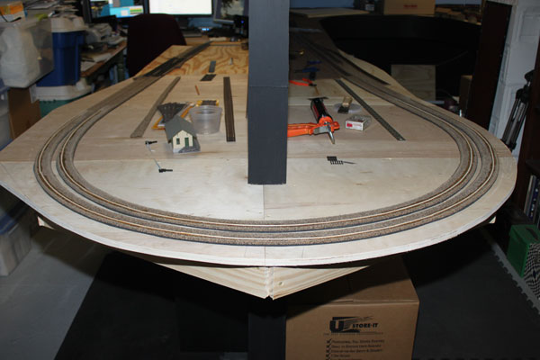
An overview of the 180 degree turn at the end of the peninsula. (8/29/10)
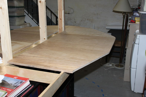
The next step was obviously to extend the existing end of tracks around the turn(oh boy!) (8/29/10)
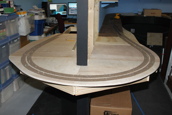
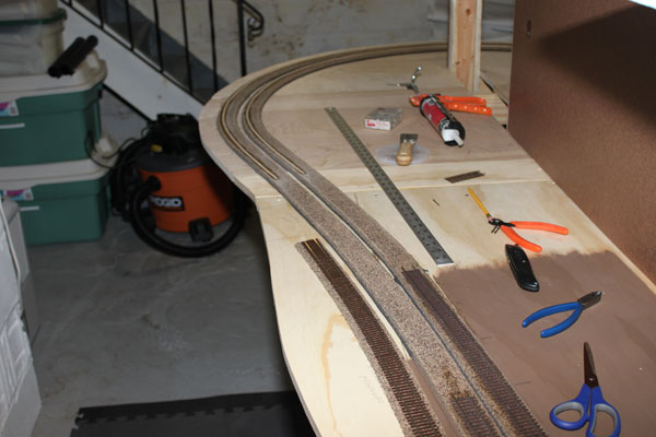
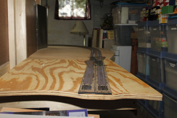
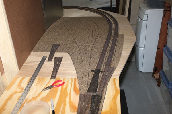
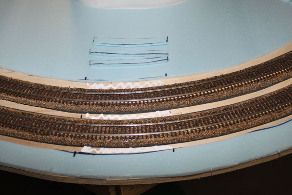
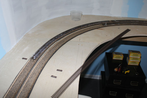
As previously, the first thing was to tack down the cork roadbed to get a good feel for the geometries of the track before committing it to the adhesive. The edges were marked with a sharpie pen and the radius of the two tracks double checked. (9/6/10)
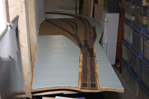
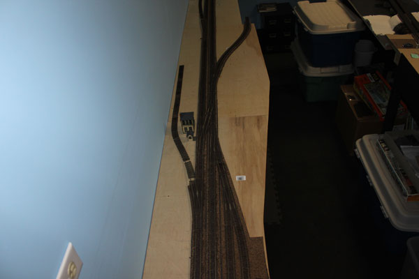
Before I got down to the business of gluing the roadbed and sub-roadbed, I marked off the approximate locations of the road crossings. I also tacked down the Point Pleasant yard and freight house area to see how it would all fit. The crossing gates are at Arnold Avenue. (9/6/10)
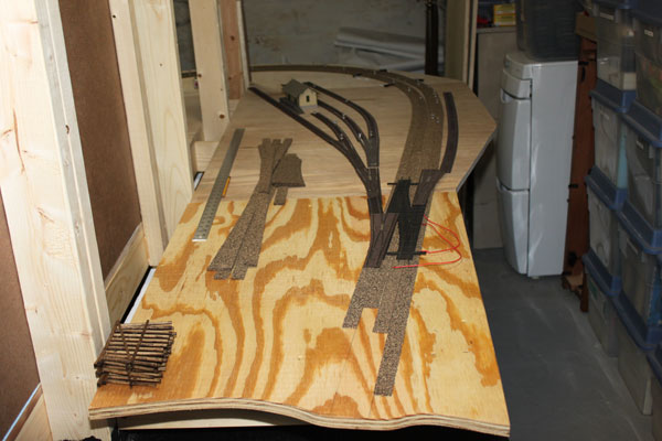
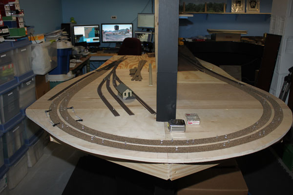
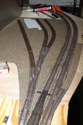
The Point Pleasant Beach part of the NY&LB in the 1950s featured a siding (to the right) for a coal and fuel dealer. On the left of the crossover was the original lead into the engine facility/turntable and yard which was reduced to a few tracks by this time for LCL and lumber deliveries. (9/6/10)
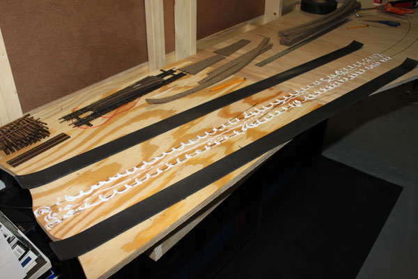
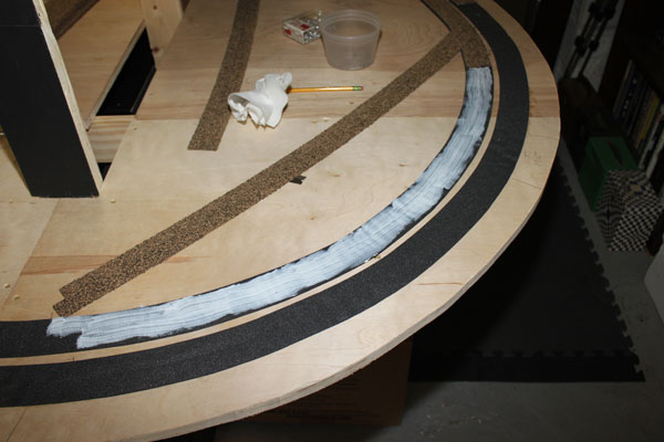
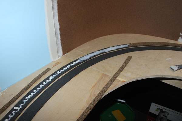
My mainline of the NY&LB consists of a sub-roadbed of foam camper tape. This not only brings the mainline up to the proper height, compared to the sidings, but REALLY dampens the track noise from locos and rolling stock. I'm completely sold on the concept. (9/6/10)
The foam tape is down on the adhesive caulk along the tangent. The plastic backing will be peeled off after it dries a bit. The width matches the cork roadbed almost exactly. (9/6/10)
Along the curves, I peeled off the backing from the foam and slit it down the middle so it's easier to form around the curves. Went down just like cork. (9/6/10)
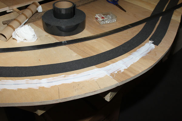
The DAP clear adhesive caulk works great on the foam, cork roadbed, and the track. Around the broad curve, I increased the track spacing from two inches to 2 and a half inches. (9/6/10)
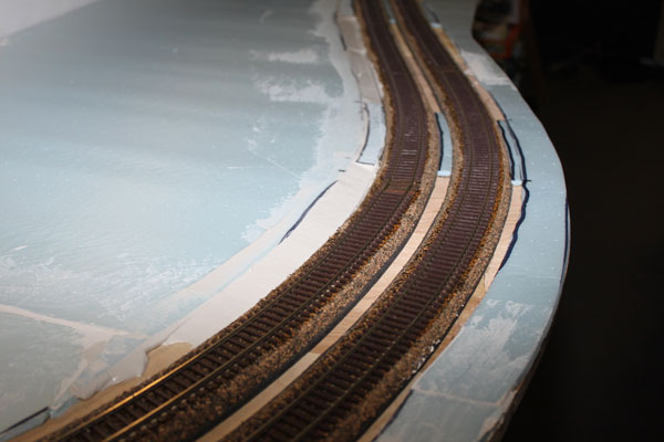
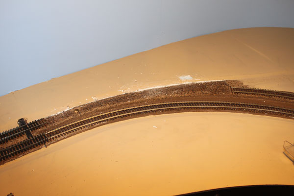
After the foam dried, I used the same process to glue the cork to the foam. Even though this 180 degree curve isn't on the prototype, it will be banked and treated as if it was. (9/6/10)
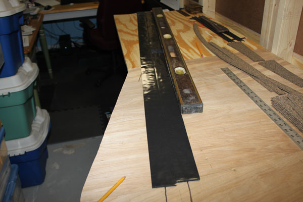
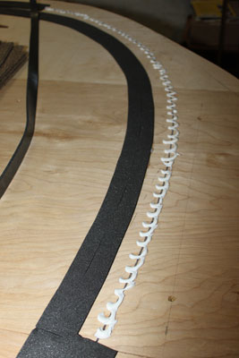
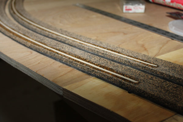
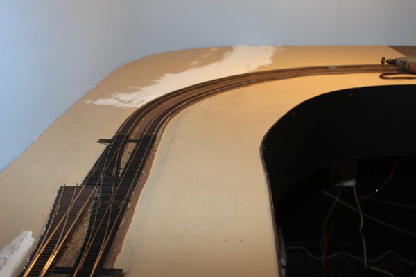
With the roadbed thoroughly dried, it was time to do some track laying. First, I needed to glue down strip wood under the outer rail of each track through the 180 degree curve. The adhesive caulk worked great for this too. (9/10/10)
Since the curves aren't too tight, I was able to leave the 2 foot long strips intact and glue/pin them in place. The 1/8th inch wide by 1/16th inch high strips of basswood are very flexible. I also made sure I had a sufficient lead into the curve with the super elevation. (9/10/10)
I then sanded the entire curve to bring the height down even further. I brought the ends down to a feather edge along the tangent. A good old sanding block worked just fine. (9/10/10)
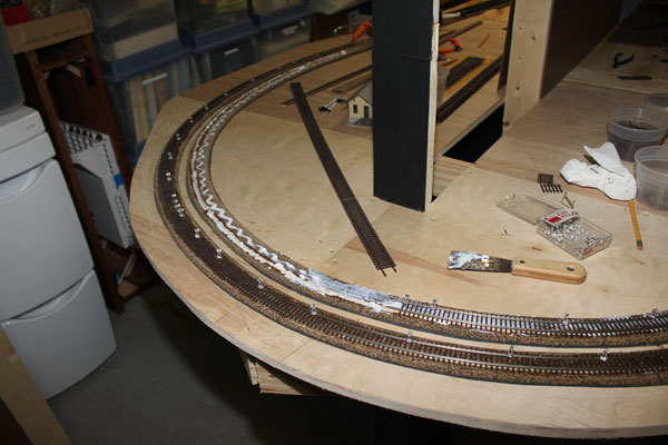
Here the tracks are being laid along the super elevated curve. A lot of pinning is needed to help keep the track level and at the proper slight angle through the curve. (9/10/10)
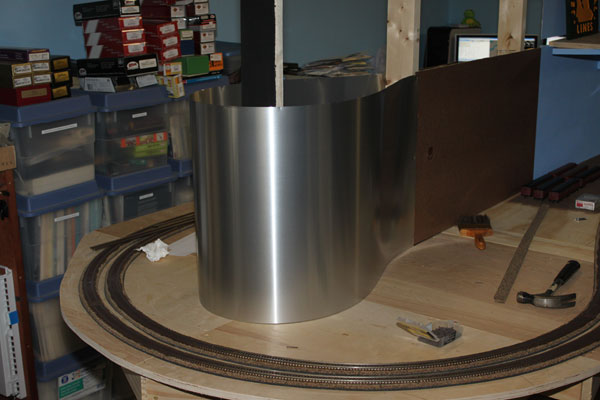
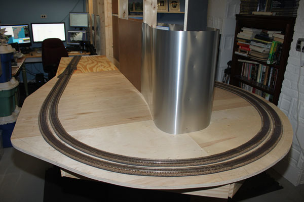
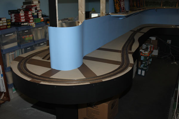
Mainline is down and now to tackle the backdrop. Since hardboard will only bend so much before it snaps, a roll of aluminum roof flashing 20 inches wide was the choice here. (9/16/10)
The flashing was easy to work with as long as I was careful not to kink it. I just cut it with scissors and nailed it to the studs with the panel nails. Nice and easy so far. (9/16/10)
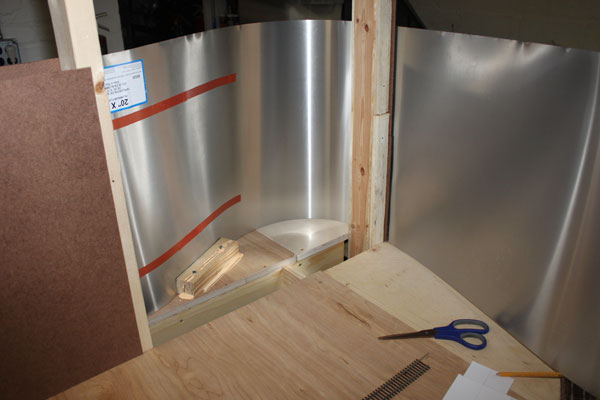
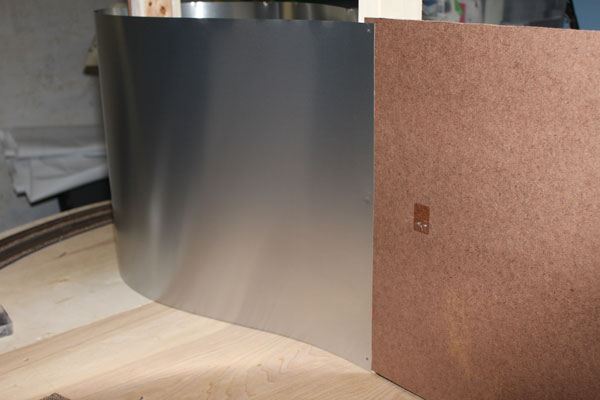
Before wrapping it around the end, I placed a support behind each side to help control the flexing of the metal sheet where it meets the table top. (9/16/10)
A view of the mainline through Point Pleasant. The end of the plywood here is the southern bank of the Manasquan River where the first bridge will be constructed. (9/16/10)
An overall view of the far side of the peninsula. The flashing nail dimples and hardboard joints will be filled in and smoothed with compound and a lot of sanding. (9/16/10)
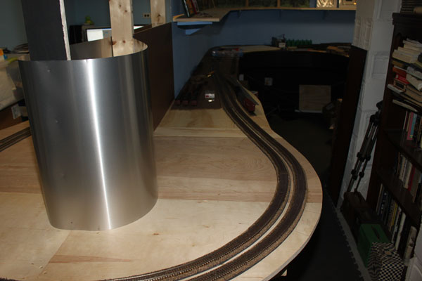
The near side of the peninsula with the mainline leading away toward Bay Head Junction. Several coats of primer and blue paint will stiffen up the flashing (I hope!) (9/16/10)
For the Point Pleasant yard tracks, I decided to put down sheet cork since the character and history of this area, a former terminal yard full of tracks, seemed to call for it. The track outlines are marked off with the circles showing the throw bar areas of the turnouts. (9/19/10)
Again, the track and turnouts in this yard are ME code 70 and sit lower than the mainline tracks. The turnout on the right is for a siding leading to the Pt. Pleasant - Bay Head Ice and Coal Co. Only the trackside portion of this company will be modeled due to limited space. (9/19/10)
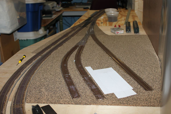
This is the Point Pleasant yard from the Arnold Avenue end (view north). The white cutout is the footprint of the CNJ Freight House and office which will be scratch-built. (9/19/10)
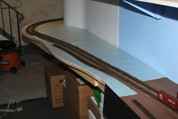
Work begins on gluing the 1/4 inch blue foam scenery base to the plywood. The previously installed foam ends with the brown paint to the right. (9/19/10)
Installation of the blue foam continues as well as several coats of primer paint on the backdrop. The aluminum flashing took the paint well and seemed to stiffen a bit. (9/19/10)
With the foam scenery base down, I had to now do some work along the tracks making drainage ditches with joint compound and tackle moving an already installed turnout at Bay Head. (9/19/10)
Part of the foam scenery base installation involves installing filler pieces along the tracks where there are grade crossings. Just brings the roads closer to track level. (9/24/10)
Here you can see the foam crossing pieces and the joint compound fillets along the track ROW. This will all be buried under future scenery so it doesn't need to look pretty. (9/24/10)
After fiddling with the scenery foam base, I decided to extend the layout fascia along the completed portion of the layout. It seems to give the layout a bit of 'meat', huh? (9/24/10)
The fascia along the end of the main peninsula. Painting it black blends it into the black wallboard under the layout and the black floor tiles, focusing attention to the layout itself. (9/24/10)
It was now time to remove the curved turnout leading into the Bond Lumber Company at Bay Head and replacing it with a straight turnout a little further east of the crossover, which is more in line with the prototype and eliminated a potential headache down the road. (9/28/10)
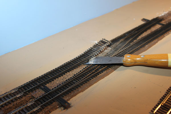
A benefit of using adhesive caulk for track laying....it gives pretty easily when you have to correct mistakes. After cutting the rails of this fast-tracks crossover, it took just a bit of coaxing with the putty knife to come up. (9/28/10)
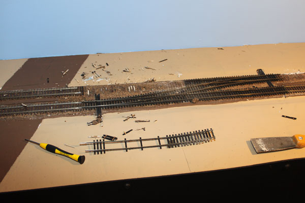
The aftermath of the work crew. A few wood and pc ties still remained, but were easily scraped off the cork roadbed. A little sanding and dressing and I'm ready to proceed. (9/28/10)
After prepping the roadbed, I spread a thin layer of adhesive caulk and installed the new turnout and section of flex track, sliding the rail joiners in from the existing track work. (9/28/10)
Installing track on a curve can be touchy, but this curve seemed to be a real pain in my a**. I finally got it pretty close using an army of pins and tacks. Whew! (9/28/10)
The ME turnout went in without a hitch and I immediately noticed the improvement in the eastbound track flow out of the yard. (9/28/10)
After everything dried, I patched up the dings and nicks I made in the scenery base as well as filling in the original siding depression for the lumber yard in the background. Next I transitioned the code 83 turnout down to code 70 for the siding and ran it into the future lumber yard. (9/28/10)
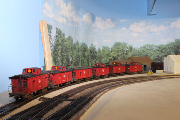
The much improved and longer Bond Lumber siding is complete. These six plywood CNJ cabins were custom built by a friend of mine out in Arizona. The CNJ would regularly park portions of the Bay Head Turner freight run on this siding during the 1950s. Great job, Bill! (9/28/10)
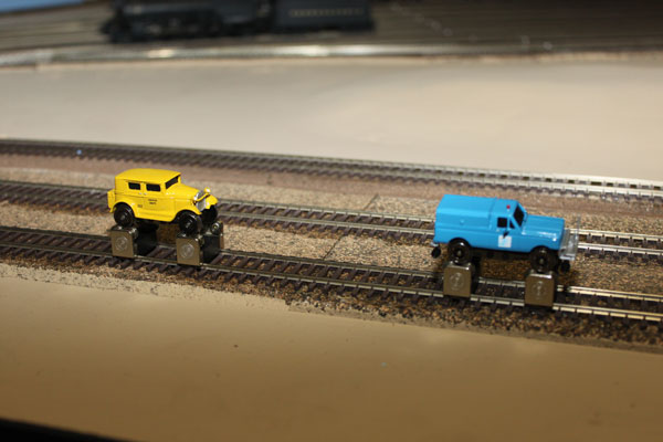
Breaking in a couple of track inspection cars (high railers). The sedan on the left is probably more appropriate for the era I'm modeling (the 1950s), while the one on the right is from the Conrail era. Construction slowed this past week due to a death in the family. But we made it through this difficult week ok. (10/3/10)
Here is an overview of the peninsula on my NY&LB line as it looks now. The roadways depict the closely spaced crossings in Point Pleasant Beach. From R to L are Sea Ave, Washington, New Jersey, Atlantic and Forman Avenues. On the left after the curve is Arnold Avenue, the main street through town. Next is some detail modeling on this part on the line. (10/3/10)
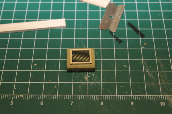
I have a brass water crane to use in the Bay Head yard, but I needed a drain for it. So I built a concrete drain basin for it out of balsa with a metal grate as seen on my work bench. (10/12/10)
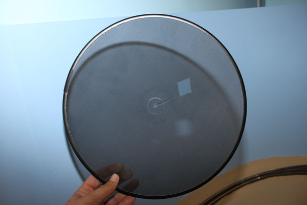
My dilemma was to find a suitable metal grate for the water basin drain. A metal splatter screen used for cooking was perfect. It was even pre-painted black! (10/12/10)
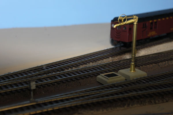
The water crane and its new drain are shown here. This was one of two water spouts used at the Bay Head yard. This one serviced the engines coming out of the coach tracks while the other was positioned to handle the steam power on the engine service tracks. (10/12/10)
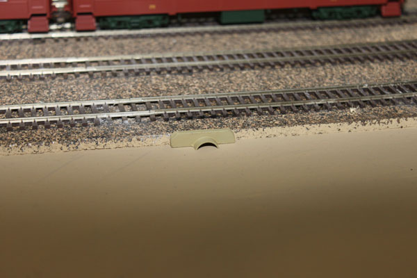
The passenger coach yard tracks at Bay Head Junction were originally built over a marshy piece of land in the 1920s. A drain pipe was installed under the yard to allow the natural and tidal flow of water to continue flowing into Twilight Lake, as shown above on my layout. (10/12/10)
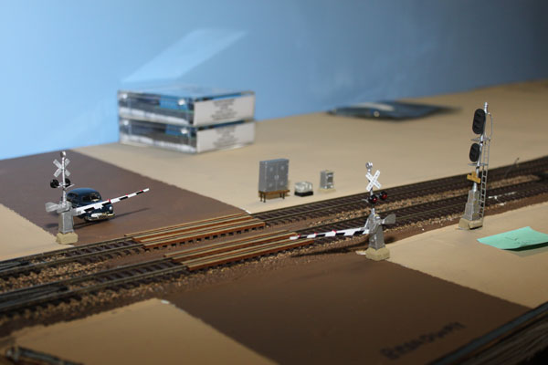
The Broadway crossing, gates, relays and batteries are shown here. Everything is just roughed up right now (meaning I can remove it all in a flash) until I'm satisfied. The block signal is a modified Tomar signal which I will touch upon later. (10/12/10)
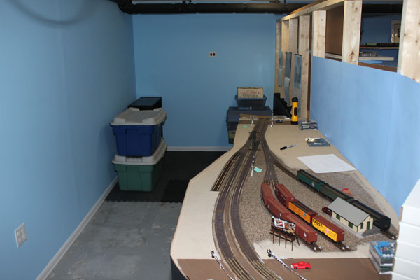
In the aftermath of everything happening over the last few weeks, I was finally able to move my office out of the basement and back to its original home. This means that the NY&LB will soon be extended around the rear and up the left wall through Sea Girt to the helix. (10/12/10)
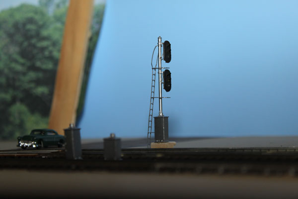
Work is progressing on the layout, but mostly in the wiring dept. I have separated the tracks into blocks, each protected by a two-head signal as shown above at the throat of Bay Head Yard. The NY&LB mostly used three over two light block signals during the 1950s (home and distant blocks). This particular signal is three over three, made by Tomar with a NJI relay base. (10/19/10)
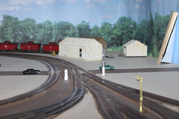
Here is another view of the signal protecting the northbound (eastbound in RR terms) tracks out of Bay Head. The boxes between the tracks operate and power the crossing flashers on Osborn Avenue (yet to be installed). The Ferry (later Bond) Lumber Co. is in the background...right now just a bunch of generic buildings. Bay Head Station will be beyond the green sedan. (10/19/10)
I wasn't sure how to handle the polarity on my turnout frogs until I discovered this handy device. It's called a Hex Frog Juicer Automatic Frog Polarity Switcher by Tam Valley Depot and it works great so far. Each board can handle up to six frogs by simply running a wire from the frog to the input terminals. The board is powered by a tap to the DCC bus. The juicer is a bit pricey, but it does the job with minimal wiring. (10/24/10)
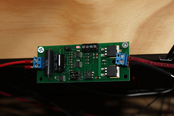
I'm dividing the layout into several power districts, each one protected by an electronic circuit breaker. Above is one of these breakers mounted under the layout, an NCE EB1 which can be configured to handle up to 8 amps of current before tripping. Set up correctly, these boards will trip in the event of a short before the power booster does, saving the booster's breaker as a back-up. The EB1 automatically resets itself once the short is removed. (10/24/10)
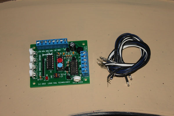
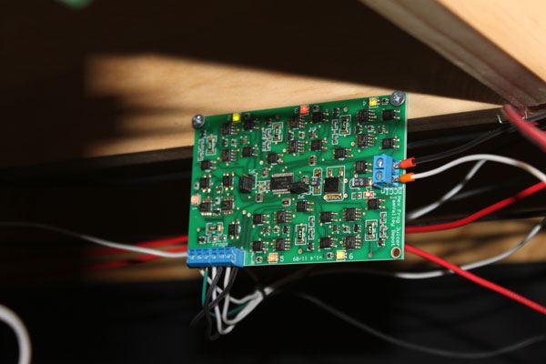
The real NY&LB had numerous at-grade crossings and so will mine. While many were only protected by cross bucks even in the 1950s, the rest were protected by flashers, hand-crank, pneumatic and electric gates as well. To automatically control these crossing devices, I'm using the Grade Crossing Pro with Infrared detection by Logic Rail Technologies. Where gates are installed, this device will also operate a Tortoise unit tied to the gates. It will also trigger a grade bell module and speaker, where needed, such as the Innovative Train Technology HQ Series Sound Module HQ300. (10/24/10)
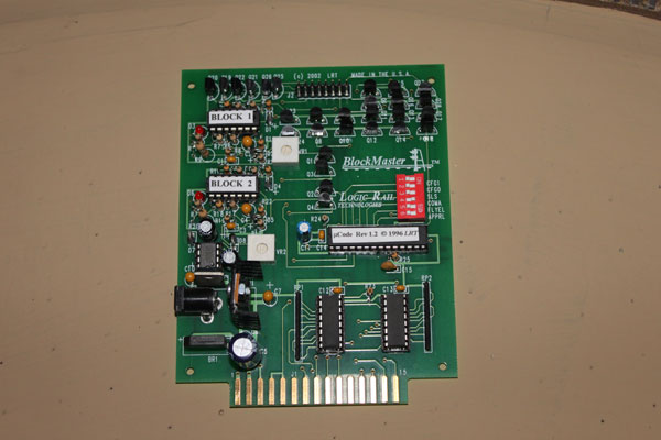
Like the prototype, my NY&LB will operate using automatic block detection. I found that the BlockMaster by Logic Rail Technologies was best suited for what I wanted to do with the signaling on the main line. It has a load of different configurations and options available. Block detection will be by current sensing, so I have begun installing resistance wheelsets on all of my unpowered rolling stock...one axle on each truck containing a 15k resister chip. I'm doing this in conjunction with bringing cars up to specs with weights, wheels (Intermountain) and couplers (mostly Kadee). Each block will be visually controlled and operated for the Engineer to obey. (10/24/10)
After a week of wiring chores on the layout, I decided to spend Halloween doing some real construction! Here is the frame for the Manasquan River...a wide and shallow body of water only a half mile from the Atlantic Ocean at this point. This is the first deviation from a basically flat terrain I've built so far on the layout. Actually, it was a nice change of pace. I also really needed to start to extend my mainline some before I can really operate some trains realistically. (10/31/10)
The plywood base for the river is down with a test piece of backdrop in place. I placed a dam on each end of the river which, along with the backdrop and fascia, will hold the "river" in place. As wide as the Manasquan River is between Point Pleasant Beach and Brielle, I had to do a substantial amount of compression to be able to fit a wood trestle, earth fill, steel girder bridge and bascule bridge into a four foot long space. (10/31/10)
Since the Manasquan River here is a tidal waterway, it has yet to be determined what the tide will be when all is said and done. The river was originally bridged by the NY&LB in 1880 on a wood trestle with a single track swing draw. The present steel bridge and Scherzer rolling bascule were built in 1911, with the wood trestle remaining at the south end of the fill, which extended between the steel and wood sections of the span. (10/31/10)
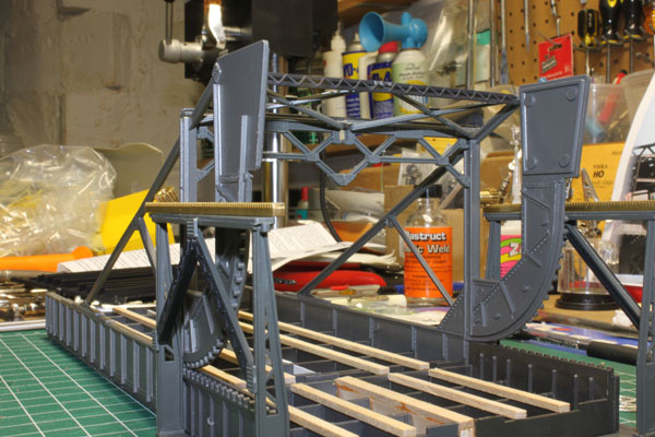
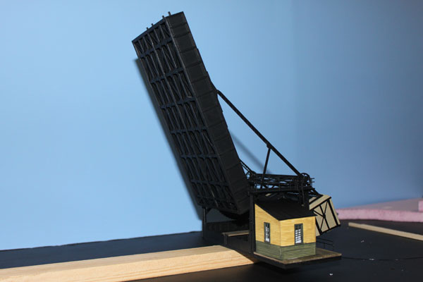
I originally intended to build the bascule bridge out of brass parts, but have since decided to kitbash a couple of single-track Pola bridges from the 1960s instead. The brass bridge will come later. Here is a rough-up of the bascule and the ME girder bridge approaches to see how things would fit. The wood bents for the small trestle are in the background. I hope to have the bascule operate just like the real thing with operating interlockings and smashboards. (10/31/10)
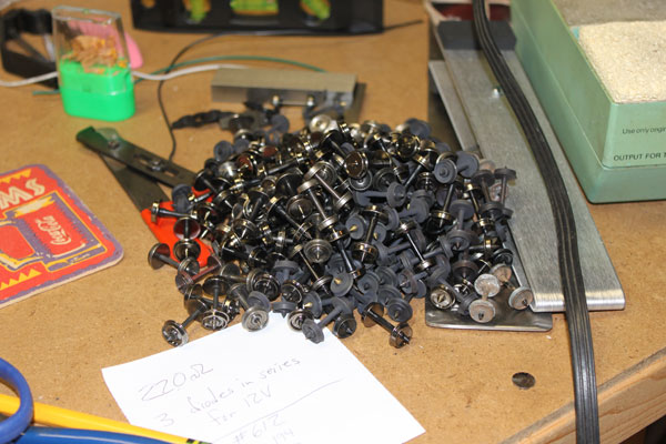
Progress on the automatic block detection continues with an almost complete change-out of wheel-sets on all of the unpowered rolling stock. This is the second pile of this size on my workbench this past week. All wheels are changing over to Intermountain with two axles per car containing a 15k ohm resistor. A bigger project (and costlier) than I thought! (11/7/10)
In the meantime, construction continues on the rolling bascule bridge for the Manasquan River crossing. Two 1960s single-track bridge kits have been combined here to make a double track span. The kits I used for this project are almost 40 years old, but the plastic parts remained remarkably straight and plumb for the most part. Lucky me! (11/7/10)
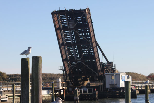
I went out today on one of the Brielle docks so to get good photos of the bascule bridge and approaches. The double-track span was single tracked in the late 1970s due to deteriorating steel girders and concrete supports. The active track now runs along the east (left) side of the bridge. (11/7/10)
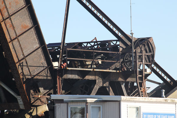
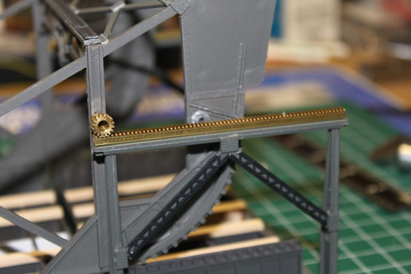
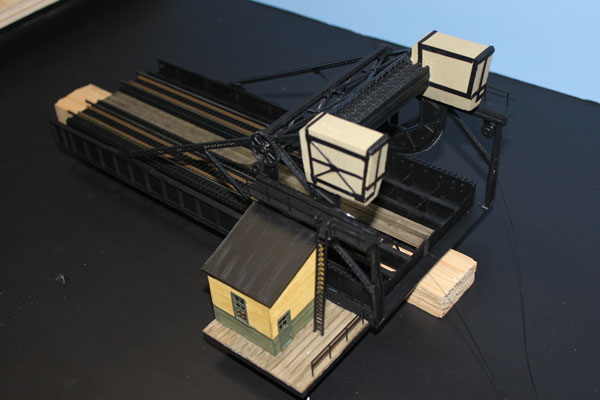
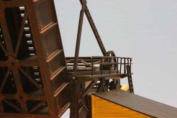
Here is a detail of the pinion gearing which enables the bridge to raise and lower. The concrete counterweights perfectly balance the bridge so only a rather small electric motor is needed to turn the gears to raise and lower the span. I hope to model as much of this detail as possible. This bascule is nearly identical to the one on the NY&LB in Morgan. (11/7/10)
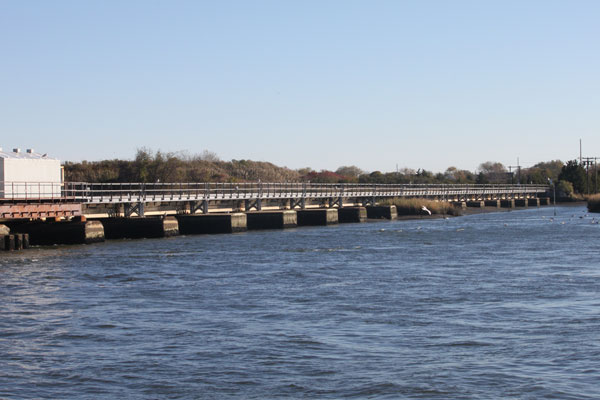
The southern approach to the bascule is shown here. The concrete footings have mostly been rebuilt over the past 15 years, however, a few of the original footings remain. It was low tide when I took these photos. The water nearly touches the bottom of the spans at a full moon tide. (11/7/10)
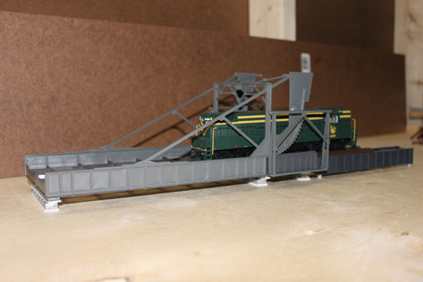
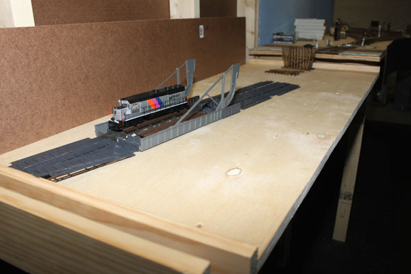
My version of the Manasquan River bridge is a bit simpler at this stage, but it's beginning to take shape. After placing a modern GP40 on the bridge last week, I decided to be faithful to the era I'm modeling and place a CNJ Trainmaster on the span this week. (11/7/10)
Here is a Micro Engineering 50 foot open-deck span on the south approach. I learned a lot while building this one ME kit...broken and warped pieces. Five more spans to build. (11/7/10)
Once the approaches are built, I'll be able to built the split concrete counterweights for the lift bridge. They need to fit between the rack supports and girder approach spans. (11/7/10)
The past week saw work continuing on building the six open-deck bridge spans (which are completed) as well as tweaking the track work. Here is the Manasquan River section along with the beginning of the 36" radius reverse curve where my office formerly resided. (11/14/10)
The north shore of the Manasquan River begins an open grid construction of the layout with the mainline on a gradually rising grade (via risers) until it reaches the helix...a rise of about 5 inches. A second deck will eventually also occupy this area between Belmar and Neptune yard. (11/14/10)
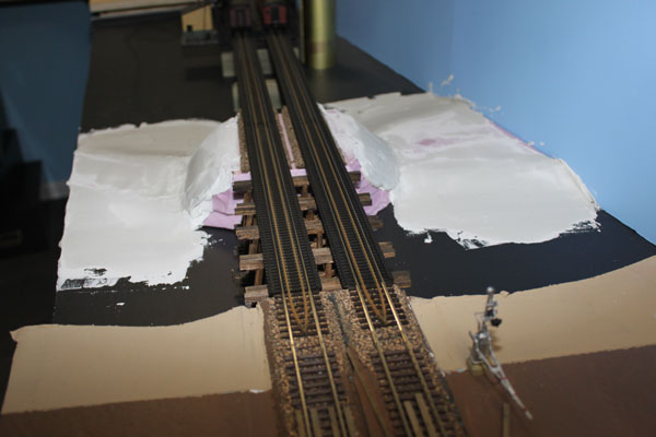
Using slabs of foam-board, I've roughed out the fill and marsh in the Manasquan River. The wood trestle is on the right. I had to make certain that this part of the layout was especially level for the future water treatment here. Looks like it will be low tide in the Manasquan. (11/14/10)
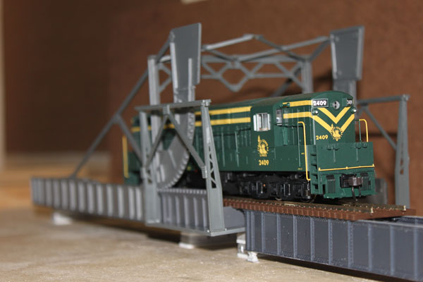
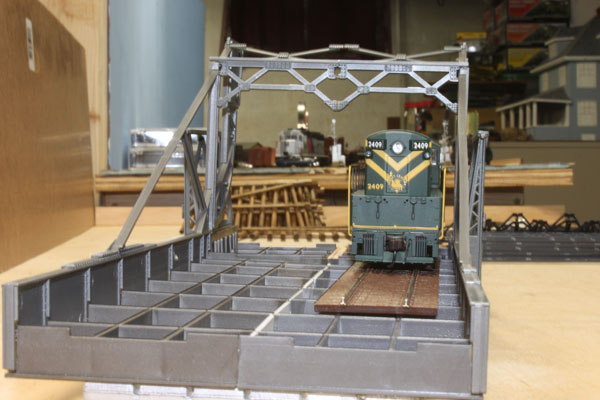
Meanwhile, construction also continued on the rolling lift bridge. The original kit pieces are gradually being embellished with rivet plates, girders and other details. The drive pinion gear and rack are shown here. Other drive gears will follow. (11/14/10)
The girders that support the tracks were beefed up using strip wood, which also brings everything to an even level. I'm still figuring out how the counter weights will be made. (11/14/10)
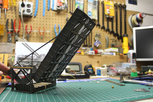
The raised bridge is pretty neat to look at. I have decided on how to realistically raise and lower the span (no, not by the pinion gears). I'm really enjoying this project! (11/14/10)
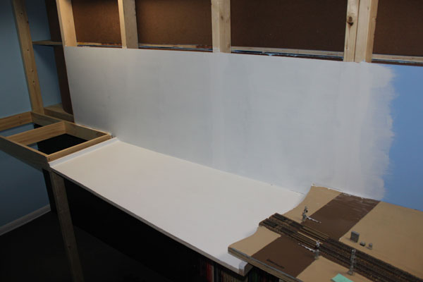
The primer coat of paint covers the backdrop and the base for the Manasquan River. Following the advice of Dave Frary, the river base will be painted black as a base color, with varying shades of blue leading to a sand color from the main channel to the shores. (11/16/10)
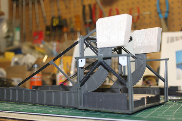
The rolling lift bridge continues its progress. More Central Valley beams have been added as well as the two concrete counterweights. These I made out of blocks of balsa with the centers cored out. The two white gussets are part of the future lift mechanism using pulleys and fishing line. (11/16/10)
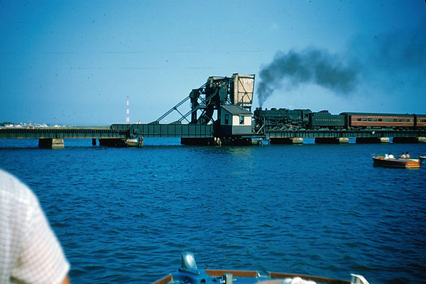
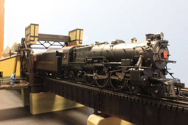
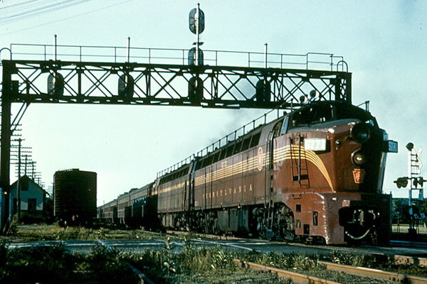
Detail work continues on the Manasquan River bridge. Here is a view of the bridge in the mid 1950s with a PRR K4s hauling a northbound commuter job. This is the appearance of the real bridge I'm trying to model. The shanty contained the "Brielle" interlocking, much like a standard interlocking plant complete with the manual levers which are now long-gone. (11/22/10)
This is a 1980s view of the wood trestle over Will's Hole Thorofare at the south end of the river crossing. This trestle was replaced about seven years ago with a concrete and steel span. This wood trestle, part of the original wooden bridge dating to the turn of the 20th Century, is also being modeled. (11/22/10)
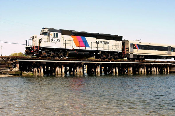
Another view of the NY&LB Manasquan River crossing after the initial rehabilitation of the bridge during the 1980s. The original steel spans were replaced with pre-cast concrete while the bridge was single-tracked due to NJT budgetary issues. (11/22/10)
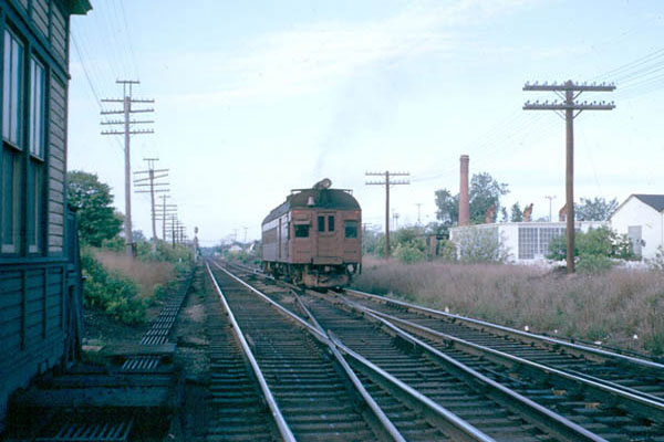
A couple of miles north was Sea Girt Junction where the NY&LB and PRR Trenton branch met. A PRR Doodlebug is seen here entering the mainline heading northbound at Sea Girt. The Sea Girt Interlocking Tower is on the right. All to be modeled in the next section! (11/22/10)
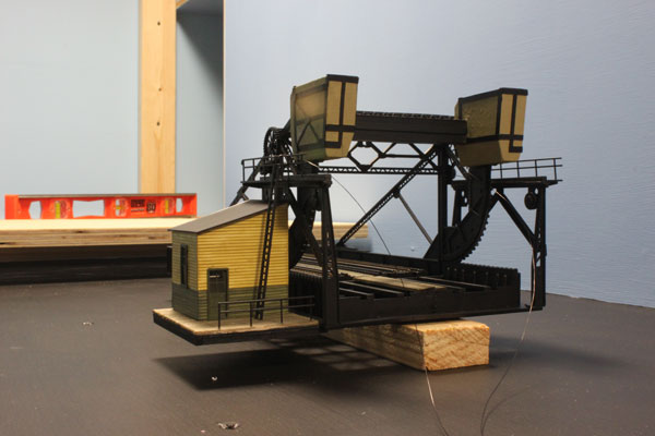
Work the past week on the layout concentrated mostly on the completion of the rolling lift bridge over the Manasquan River. The structure is about 90 percent complete. (11/28/10)
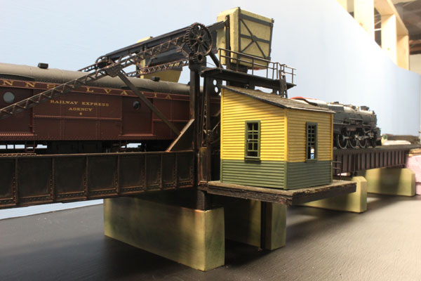
I first built the bridge tender shanty out of cardboard to make sure the dimensions looked good before constructing this one here with Tichy windows and standard CNJ paint scheme. (11/28/10)
I started this bridge with the intention of it being only temporary, but since it went together so well and is pretty faithful to the original, it will stay on the layout permanently. The bridge track is from Walthers. (11/28/10)
The two fine lines on the right are part of the lift mechanism which will make the bridge fully operational. They will tie into a high torque, very slow rpm motor connected to an animation circuit located under the layout. (11/28/10)
The remaining work on the bridge involves weathering the steel beams with Rustall and other parts of the bridge with powders. The shanty still needs a bit of work too. (11/28/10)
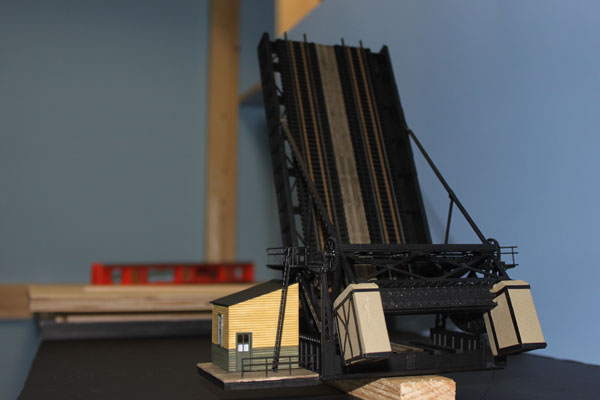
The shanty will get an interior light and navigation lights need to be added to the bridge. Now that this project is winding down, track and bench work will resume at a normal pace. (11/28/10)
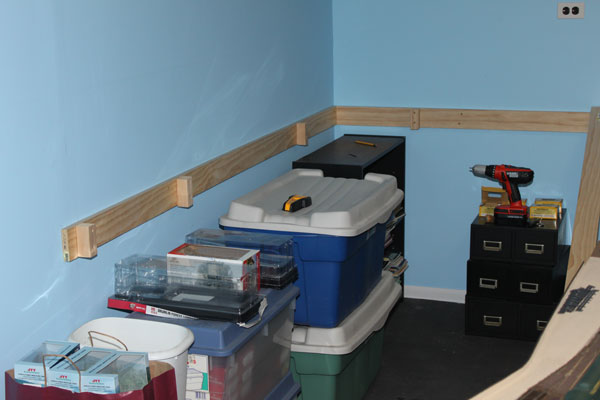
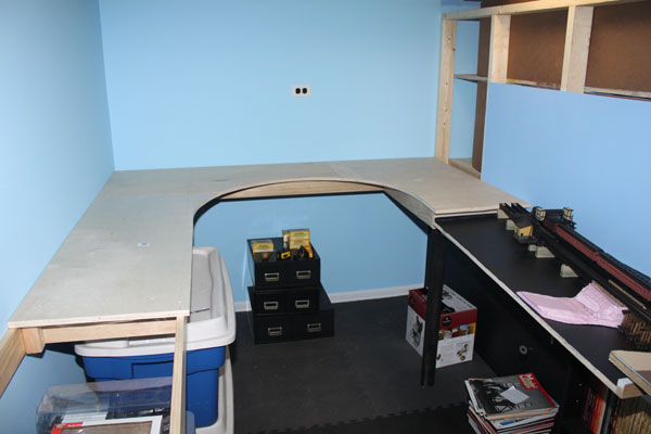
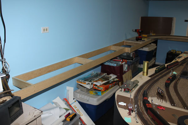
Expansion of the lower level of the layout continued this past week with 1x4 headers attached to the walls with 2x2 blocks. It was good to get back to layout construction. (12/5/10)
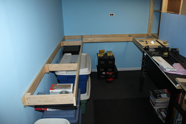
The frame is done and is solid as a rock. The end of the frame is about where Sea Girt will be and is halfway to the helix to bring the layout to the future upper deck. (12/5/10)
An overall view of the construction. Since this part of the prototype is still rather flat, I decided to go with the plywood top instead of open grid. Especially since the Sea Girt Junction and freight yard are located here (need I say more?) (12/5/10)
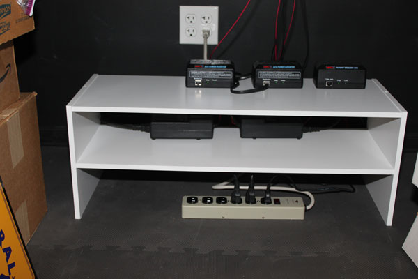
In the meantime, I cleaned up the layout control area with a cheapo closet shelf unit from WalMart. The MRC wireless DCC base unit and district boosters are on top with the power supplies on the bottom. It makes for a neat and functional setup. (12/5/10)
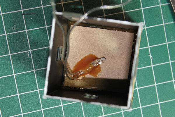
Work also continued on the rolling bridge tender shanty. Here, a warm white led has been glued to the interior ceiling. This led came from a string of Christmas lights. I sanded down the end of the led and sanded the sides to diffuse the light. (12/5/10)
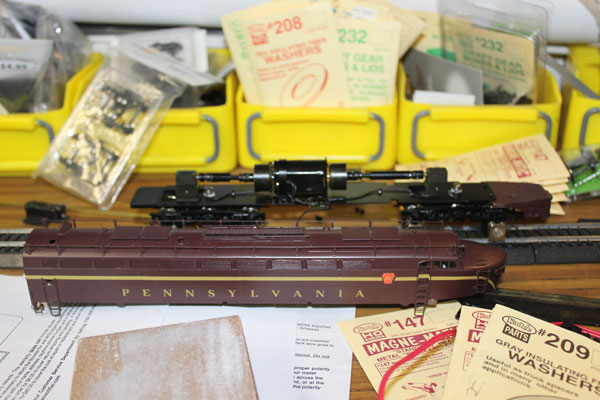
Here is an Oriental Limited Baldwin BP20 Shark passenger diesel apart on the bench waiting for an upgrade to DCC and sound from QSI. The already-installed can motor with dual flywheels and ample space should make this conversion a fairly straightforward task. (12/5/10)
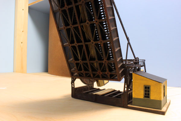
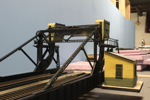
Weathering of the Scherzer rolling lift bridge has been completed (except for the bridge tender shanty which still needs a smoke stack, roof shingles and weathering). I used a wash of Rustall over all of the steel parts of the bridge with realistic results. (12/9/10)
Being in a marine environment, the bridge has always been the target of rust and corrosion. I had to be careful not to strip off the black water-based paint with the Rustall. Some did come off, but it gave an added effect of weathering. (12/9/10)
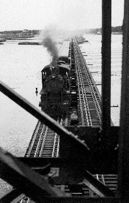
Work on the layout slowed down this past week while holiday decorating took front stage. The bridge tender shanty for the Manasquan River bridge was completed. Here is a view of the span looking south from the draw about 1930 with CNJ Camelback 623 and three coaches. (12/13/10)
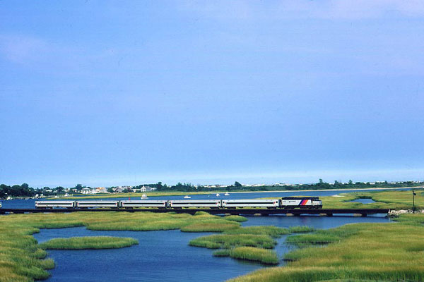
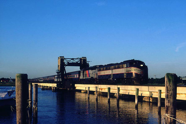
A more recent shot of the same bridge shows how the marshes have gradually taken over part of the river beginning in the 1950s when the present Route 35 highway bridge was built upriver. A NJT FP40 and five coaches cross the span. The draw is to the left. (12/13/10)
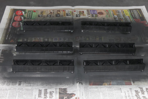
Eager to get the track work installed north of the Manasquan River, the pace picked up on finishing the trestle and steel drawbridge over the river. The ME 50 foot spans are shown here getting the first coat of paint. (12/17/10)
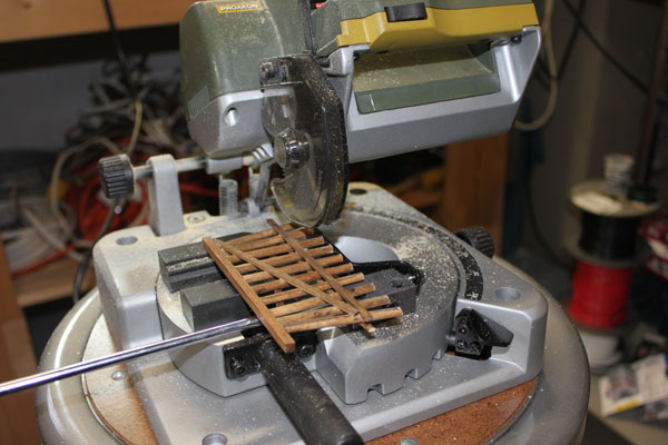
The trestle bents needed to be cut down to the proper height. These are double track bents made by Grand Central Gems and are really nice. This wood trestle on the real line was just recently replaced with a concrete span. (12/17/10)
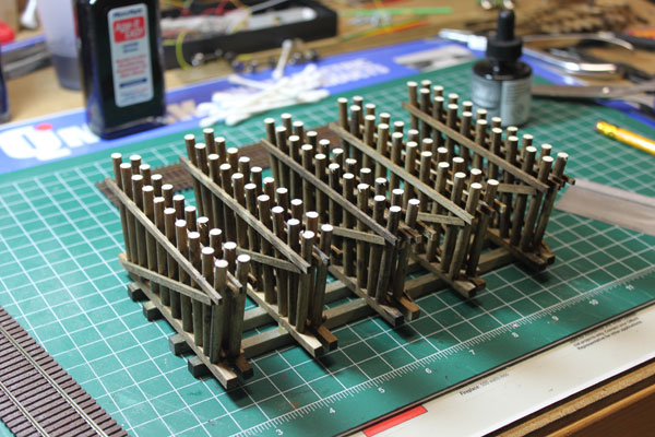
The prototype trestle had the bents doubled up and spaced close together. I glued everything together upside down on the work bench so the top was level. (12/17/10)
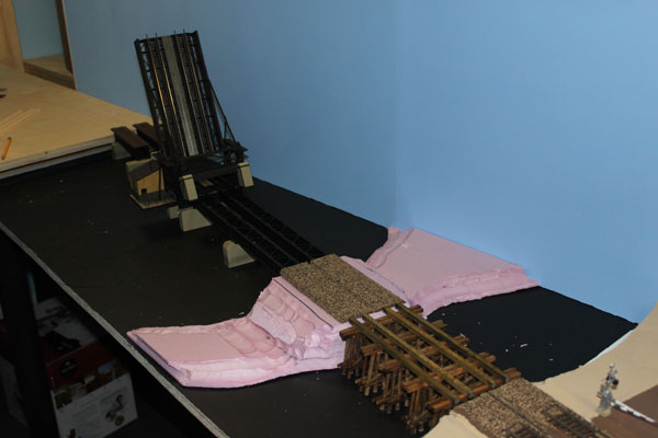
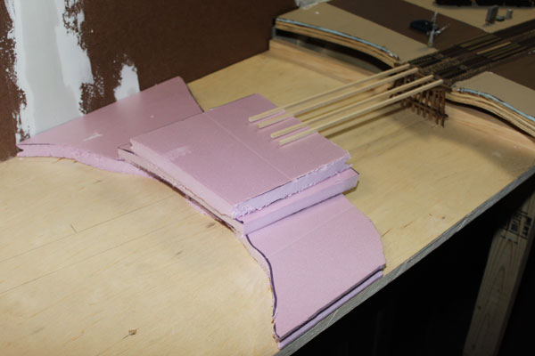
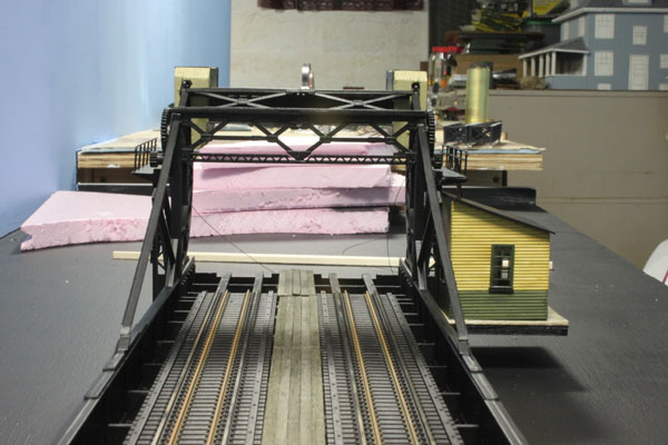
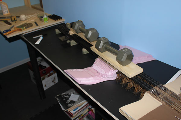
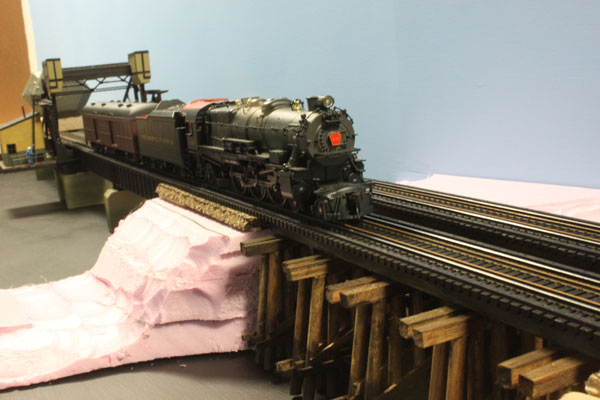
The bridge is very close to having the track installed. The pink foam island is a compressed version of the real fill in the middle of the prototype with marshes on either side. (12/17/10)
Work on the bridge continued with a parade of last minute details before the track could be glued down and bring it all together. Bridge track needed to be painted and sized while all of the weathering on the concrete piers had to be sealed with Dullcoat. The mechanism for the lift was especially challenging with the two nylon lines run through tubes and through the plywood base in a way so the future 'water' won't interfere. (12/18/10)
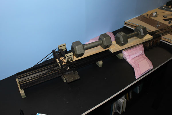
All of this extra work and handling of the model involved railings and such breaking off. But in the end, the track went down more level and straight than I hoped. Two ten pound weights will remain in place overnight. I used the usual caulk on the cork roadbed and Goo on the other spans. The far north span will be installed when work on the roadbed starts at the 180 degree turn. Further detail work on the bridge and river will occur when I reach the scenic portion of construction. 12/18/10)
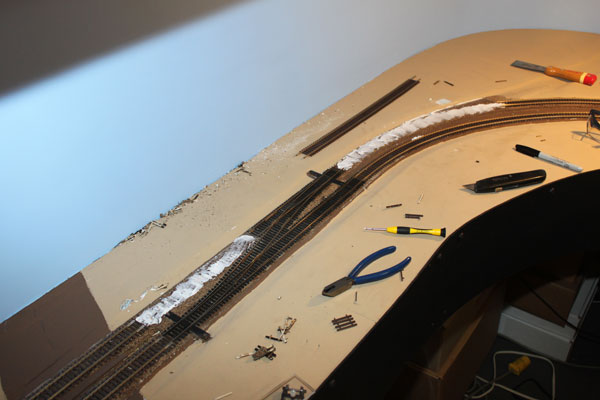
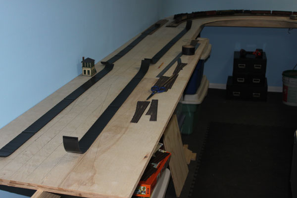
With the Manasquan River bridge out of the way, work progressed quickly on the bench work. The river is on the right...Sea Girt Junction is on the left. 12/19/10)
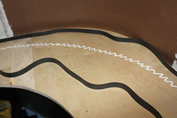
The wavy lines are the split foam camper tape which I use for the sub-roadbed. DAP clear adhesive caulk is the tried and true method...goes on white, dries clear. (12/19/10)
With the camper tape down, the cork roadbed is applied the same way. The foam tape really does dampen the noise and also raises the main line to a prototypical height. 12/19/10)
I decided to finish off the lower lever bench work to the point where the helix will be located (extreme left). In the background are the hardboard coved corners. (12/19/10)
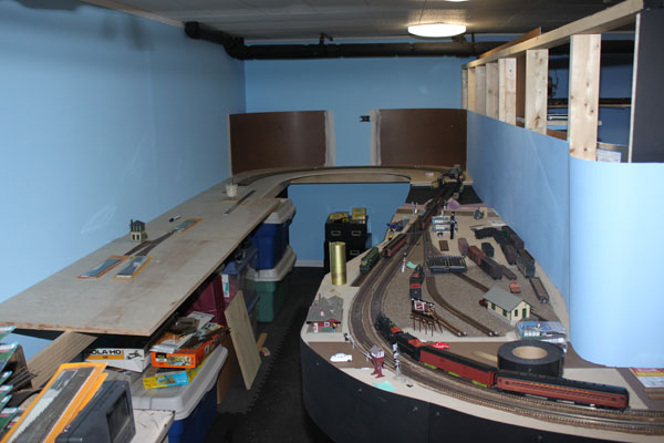
Here is an overview of this part of the layout with Sea Girt on the left and Pt. Pleasant Beach on the right. In the center is a stand-in for the Point Beach station...an Atlas Rockville Station model that was on my first layout back in the early 1970s. (12/19/10)
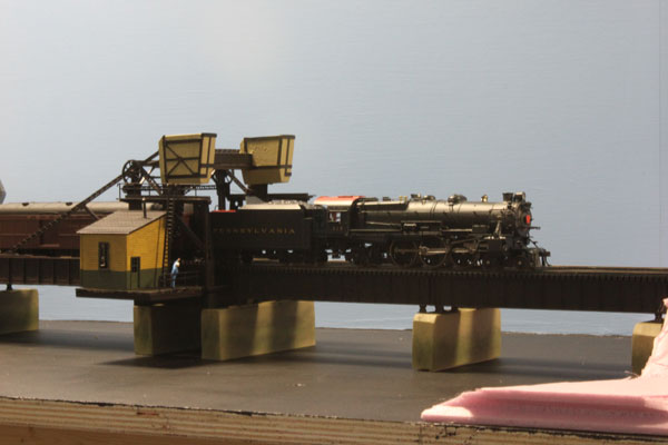
A PRR K4s Pacific and baggage car cross the Manasquan River bridge approaching Point Pleasant. When the river water is added, the piers will be half the height above water line. The water will be about level with the pink foam marsh on the right. (12/19/10)
Some shots of the PRR Pacific on the bridge. (12/19/10)
This scene was a daily occurrence on the NY&LB during the 1950s. (12/19/10)
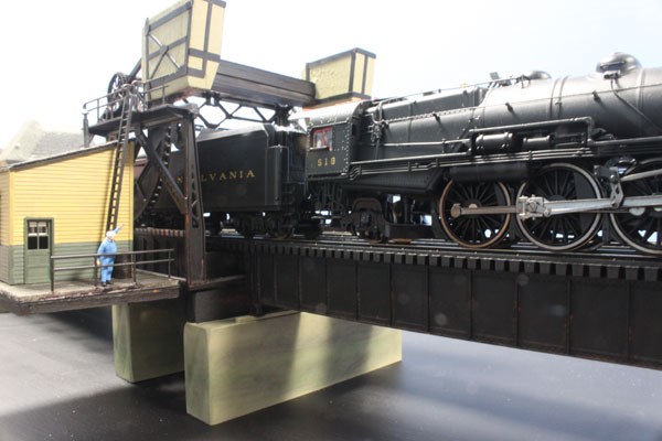
The bridge tender waves to the engineer. (12/19/10)
The wood trestle over Will's Hole Thorofare groans as the K4 crosses the span. (12/19/10)
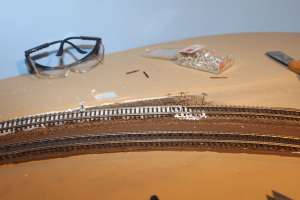
Work this week included the roadbed around the curve and track installation which is super-elevated. If I was going to model the Manasquan Station, this would be its location. It was a tough decision not to model it due to a lack of linear space. (12/22/10)
Work also continues on the backdrop and the Manasquan River island and fill. Several layers of sheetrock compound works just fine over the foam base. Before I go much farther though, I'll need to build the wood and concrete abutments for the trestle. (12/22/10)
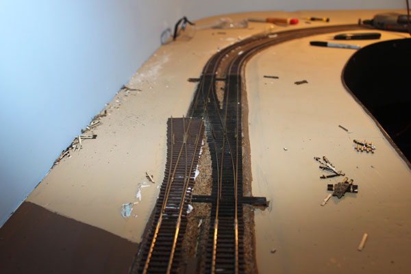
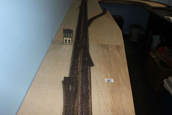
Hope everyone had a great Holiday! I managed to do a bit of work on the layout over the weekend...mostly getting trains and track in good shape for holiday guests. I also proceeded with installing roadbed in the Sea Girt area (above). The Walthers interlocking tower is a stand-in for the future scratch-built PRR SG tower. Slimming the plywood top is next. (12/27/10)
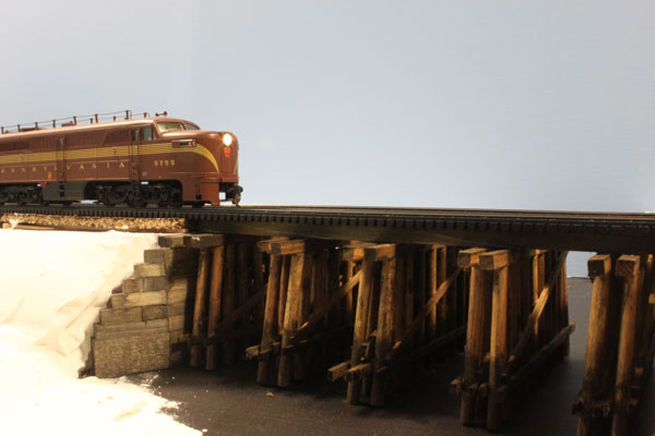
A PRR Alco PA heads westbound toward Point Pleasant in 1956. The wood abutment has been installed on the north side of the trestle spanning Will's Hole Thorofare, part of the Manasquan River. The white plaster on the embankment could pass for snow in this scene. We had 25 inches of the powder dumped on us this weekend here at the Jersey Shore! (12/27/10)
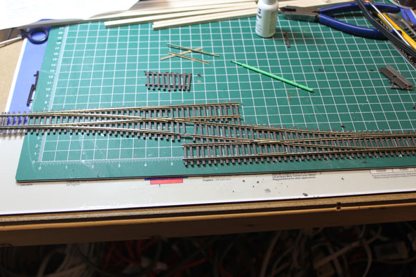
I needed a crossover for Sea Girt Junction and built this one out of a couple of ME #6 turnouts. The two previous crossovers I installed at Point Pleasant and Bay Head were from fast tracks. Although not quite as exact, this alternate will do nicely. (12/30/10)
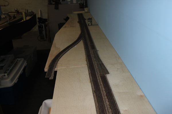
A couple of snow days from work really help in the layout construction dept. I finished laying track in Phase 1 of the layout, the lower level through Sea Girt. The Freehold and Jamesburg branch is on the left, which will continue into a single track stage along the front of the layout. (12/30/10)
The turnout on the left at Sea Girt will run to the NJ State Encampment siding to the rear of the tower. On the right...the two freight sidings and signal bridge wait to be built. (12/30/10)
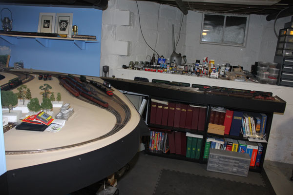
Here is a view of the Bay Head loop and the off-line staging area of the layout. Haven't shown any pics of the layout here in a while. See the snow in the basement window. (12/30/10)
An overview of the layout so far from the end of the blob in Point Pleasant Beach to Bay Head Junction off to the right. (12/30/10)
Another overview of the layout from the end of the blob at Point Pleasant Beach to Sea Girt off to the left. Track wiring at Sea Girt is the next project this weekend. (12/30/10)
With the track wiring completed, trains can now run from Sea Girt to Bay Head on my NY&LB line. This overhead view shows the two track mainline with PRR SG Tower in the center. The CNJ/PRR two track freight yard is at the bottom. To the left is the siding leading to the military camp power house while to the right is the PRR Freehold and Jamesburg line to staging. (1/2/11)
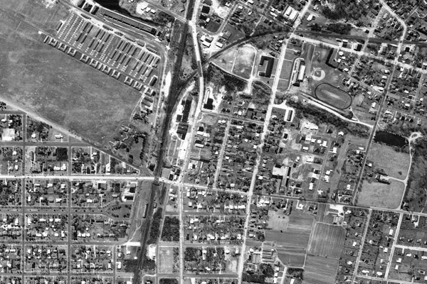
This is an aerial of the real Sea Girt Junction in 1962...same perspective as the model photo on the left. North is to the bottom of the photo. The open space on the left is the Sea Girt Camp with the power house at the top. The PRR branch line is visible to the right in its final year of service. The highway bridge over the PRR line is State Rt. 71, which will be modeled on the layout. (1/2/11)
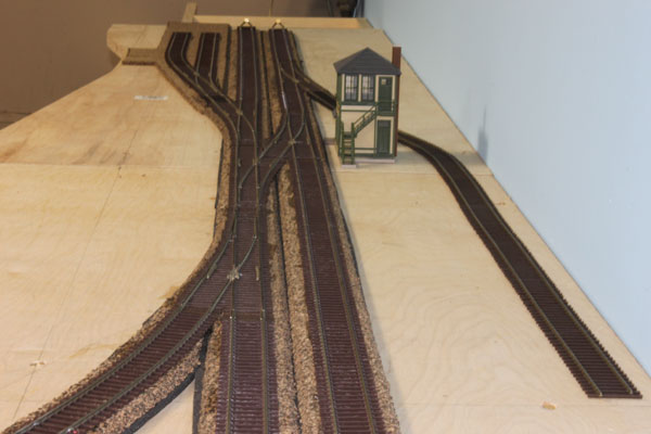
Sea Girt Junction looking north shows how the track work was laid out. Where the tracks spread out to four wide is the Washington Boulevard crossing and just beyond is the future CNJ signal bridge. The CNJ freight station on the left and the Sea Girt passenger station to the right of the mainline will be modeled just before the mainline enters the helix to the upper deck. The military camp siding (right) will be finalized once the foam ground base is installed, while the temporary Walthers SG Tower stand-in will be replaced with a scratch-built SG Tower. (1/2/11)
A PRR Baldwin BP20 Shark double lash-up at Sea Girt heads toward Bay Head in 1957. This signal bridge is being modeled from two NJI double track bridges. The freight house is on the left and the road crossing is Washington Blvd. SG Tower was removed in 1968, five years after the Freehold & Jamesburg branch was torn up west to Farmingdale. The signal bridge was removed around 1964 when the freight sidings were reconfigured to a single team track. The State Route 71 overpass was finally removed in 1972, ten years after the Freehold line was abandoned. (1/2/11)